Hexrod Documentation
Table of Contents
- Program Origin and History
- Overview
- Start Here
- First screen: entering rod fundamentals
- Second screen: entering rod taper
- Other ways of entering a taper
- Entering rod stresses
- Entering a straight taper
- Entering a Powell taper
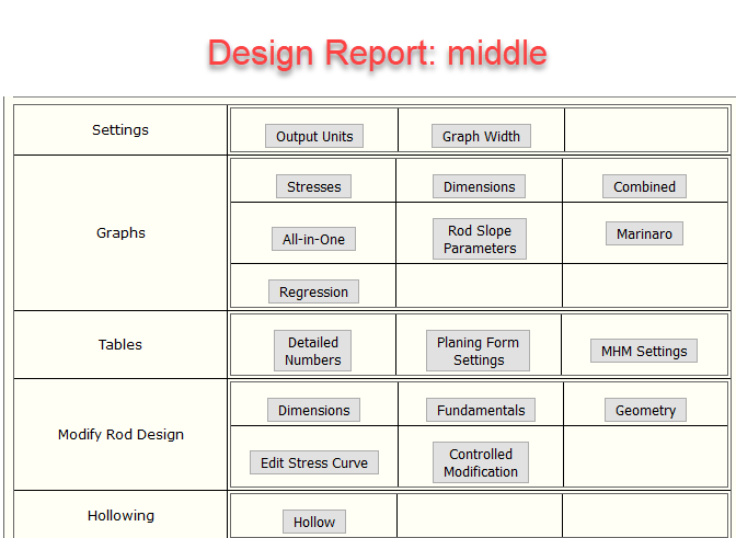
- Design Report Screen
- Settings
- Graphs
- Tables
- Modify the rod
- Dimensions
- Fundamentals
- Geometry
- Controlled modification
- Editing the stress curve
- Hollowing
- Modification by deflection
- Rod Libraries
- Creating a library and saving a rod
- Comparing rods
- More detail on special topics
- Various definitions, assumptions and quirks
- Specifying ferrule weights
- Powell taper calculator
- Modifying fundamentals
- Hollowing
- Static deflection
- Casting deflection
- Modify rod by deflection
- Bokstrom's Controlled Modification
Program Origin and History
Hexrod is a set of tools to aid in the design and analysis of
tapers for split cane (bamboo) flyrods. At the core is the stress
analysis conceived by Everett Garrison. Stress analysis is a widely used
method to analyze, compare and modify tapers. Besides stress analysis, Hexrod also
implements John Bokstrom's method of controlled modification, and does more
mundane tasks such as graphing tapers, computing ferrule sizes and form settings
for ordinary planing forms and Morgan hand mills. In Hexrod, you can also
save your tapers in a library for later retrieval and use.
This online version of Hexrod is based on Wayne Cattanach's Hexrod program, Rev 7-92,
which was graciously supplied by Wayne. It uses Web "forms" to
pass information between a set of cgi scripts written in Perl.
Wayne's Hexrod program was based on Everett Garrison's formulas,
published in "The Book".
I was also inspired by Bruce Conner's Windows version of Hexrod.
For in introduction to stress analysis as used in Hexrod, see this
document.
You can find an archive of information about cane rods, the Hexrod
program, and cane rod tapers at Jerry Foster's excellent
Rodmakers Web Site. Jerry's site has a paper by Wayne describing the
math behind the
Hexrod program.
Some important milestones:
- December 17, 1996: First released.
- May 2002: Complete rewrite of the program, adding many new features.
- July 2002: Added the ability to set up private taper libraries.
- Spring 2009: Major revisions, most important a rehosting to a commercial
web server and moving all rods and user libraries to a MySQL database.
- July 2015: Added rod slope measures (Bokstrom RAV and LWV).
- September 2015: Better support for metric data users and some simplification
- November 2015: Compute rod stress for a hollow rod.
- August 2018: Modify a rod based on Bokstrom's Controlled Modification.
- April 2020: Calculation of static and casting deflection, and modification
by holding constant casting deflection.
- April 2021: Changes to change geometry operation
Before using Hexrod, take a few minutes to study this flowchart of its
main parts:
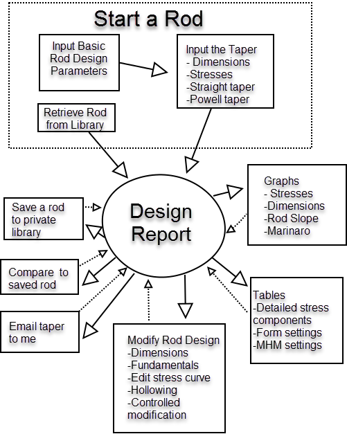
There are three ways to get a rod taper into Hexrod for analysis:
(1) enter the details of the rod, including its taper; (2) retrieve
a rod previously saved in a Hexrod private library; or (3) retrieve
a classic rod from the Rodmakers library.
Libraries will be discussed below.
If you enter a rod, the first screen is where you enter the basic
rod parameters, what I like to call fundamentals:
things like the geometry (hex, penta, or quad), rod length, line weight and number of
pieces. You can also choose between American and metric units, and the pixel width
of graphs, depending on the size of your computer screen.
Then you have to enter the taper. There are four options: (1) enter the
actual rod dimensions at points along the rod (e.g. five inch intervals); (2)
enter the stress curve (for the advanced user); (3) specify a straight taper;
or (4) specify a taper from the Powell taper system.
After an extra click or two, you are at the Design Report page. You
have specified all the necessary details of the rod, and it is ready for
analysis or modification. This is the central page of Hexrod; you will always
return to this page.
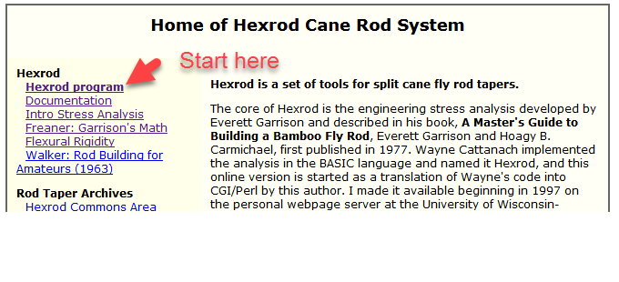
The opening screen has a link to the Hexrod program. It also has links to
other useful things, such as documents, libraries of tapers and guide spacing programs.
We will return to some of these later.
The first input page
is titled
Basic Rod Design Parameters. For short we call these the
fundamentals. Half of these are self explanatory. The others
are used in the Garrison stress calculations.
Saving and retrieving a rod from a library will be
discussed below.
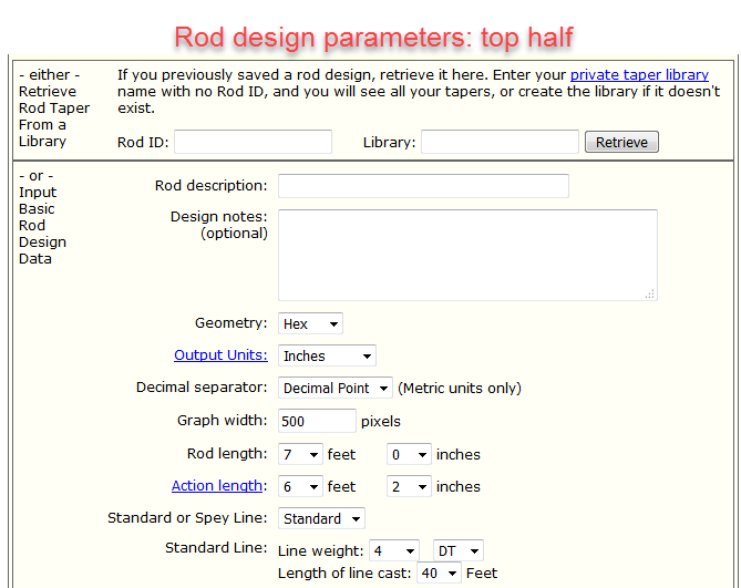
These are the items on the top half of the Fundamentals screen:
- Rod description A short name for the taper.
- Design notes Whatever you need.
- Geometry Hex Penta or Quad
- Output units
- Decimal separator
- Graph width For display on your computer screen.
- Rod length
- Action length To top of grip or butt swell. This is where stress calculations end.
- Line details Stress calculations depend on the weight of all the rod components
and the line. If you are interested in the stress numbers, put realistic values
in here.
- Standard or spey line
- Line weight & type
- Length of line cast
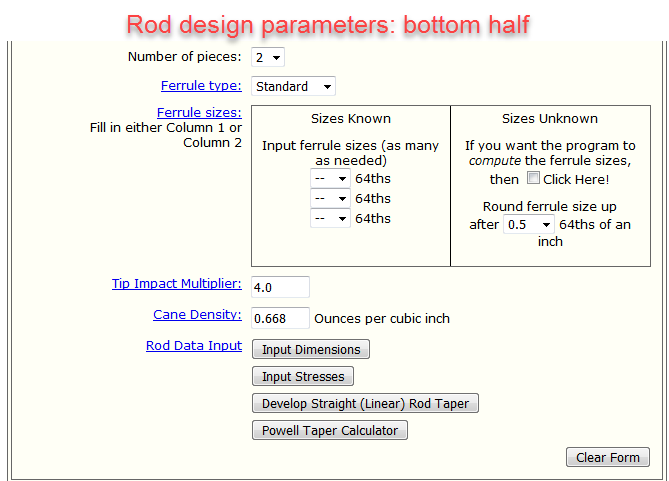
These are the items on the bottom half of the Fundamentals screen:
- Number of pieces 1 through 4. All rod sections are assumed to be the same length.
See note below on inputting rods with unequal sections.
- Ferrule details Ferrules are a major source of weight, and figure large in the
stress calculations. Ferrules are assumed to be nickel silver, either standard
length or truncated. For a rod with ferrules of a different type see the
notes below. There is no special provision for step-down
ferrules, although one may be forthcoming.
- Ferrule type Standard or truncated.
- Ferrule sizes In 64-ths if known.
- Compute ferrule sizes If ferrule sizes unknown; you must specify where to round
up to the next 64-th size from the flat-to-flat dimension.
- Tip impact multiplier For computing stresses; see the stress analysis document for discussion; rarely changed from value of 4.
- Cane density For computing stresses; rarely changed from value of 0.668.
- Rod data input This is where you enter the rod taper, by one of four methods:
The most common method of getting your rod taper into Hexrod is to enter
rod dimensions at measured points along the rod.
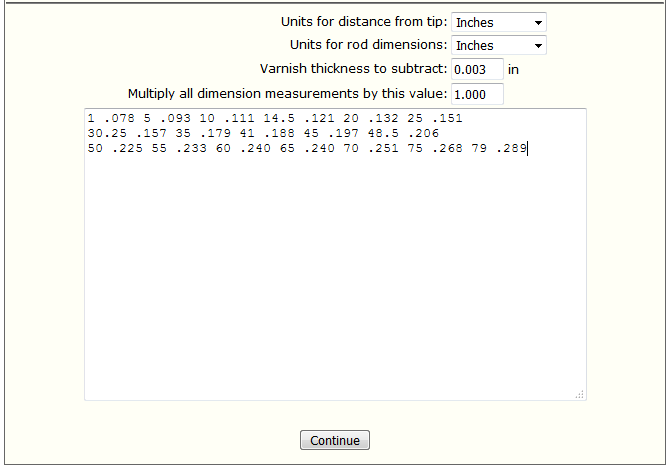
Pairs of numbers are entered into the box, with first number being the distance
from the rod tip (of the assembled rod) and second being the rod dimension at that
point. Distances do not have to be at any particular spacing (although five-inch
intervals are common) nor do the pairs need to be in any order.
You can specify input units, amount to substract from dimensions (e.g. varnish),
and a multipler. The top of the screen has more details.
After clicking Continue, the data will be checked for obvious errors
and dimensions interpolated to one-inch points will be displayed for you to
check.
It is possible to get rod dimensions indirectly by starting with stress
values and working backward. This option is for the hard-core user.
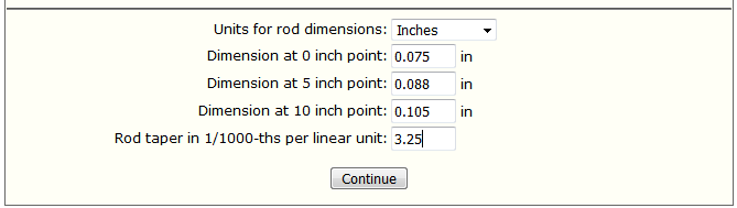
To start with a simple straight taper, give the dimensions at
the 0, 5 and 10 inch stations and then a taper slope for the rest of
the rod:
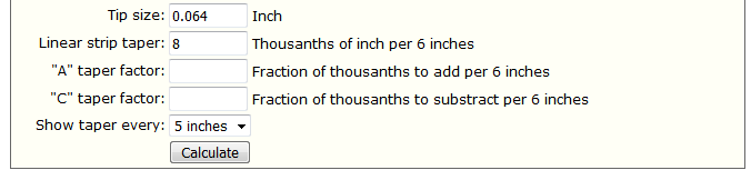
You can calculate tapers in the Powell "A", "B", and "C" taper schemes. This is
based on the article by Ed Hartzell in
The Planing Form, number 54 (1998).
More detail on Powell tapers is
below.
See also the
paper by Mike McGuire on his website.
Once the rod fundamentals and taper has been entered, Hexrod takes you to
the Design Report screen. The top of the screen gives the rod fundamentals
and taper: dimensions and stresses at five inch intervals,
ferrule locations and sizes and tiptop size.
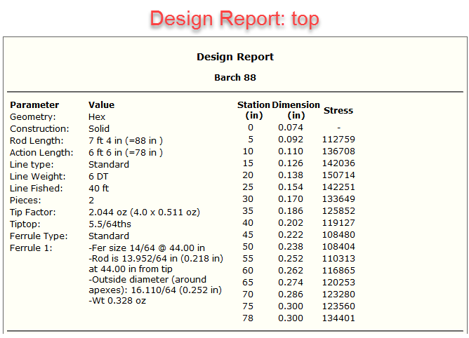
The middle of the screen gives you options to get additional information
in the form of graphs and tables, and to modify the rod taper to achieve
some end. All of these options return to this page after completing their task.
These are the graphs, most are self explanatory:
- Stresses: the usual Garrison-style stress curve
- Dimensions
- Combined: both stresses and dimensions on a single graph
- All-in-One: stress graph, dimension graph and a table of dimensions
at five inch intervals
- Rod Slope Parameters: these are related to John Bokstrom's rod analysis
method; see details below
- Rod speed: numeric score for rod speed based on stress values (my invention)
- Marinaro: as described in Whittle and Harms:
Split and Glued by Vince Marinaro
- Regression: Linear, quadratic and cubic regression of rod dimensions against
the stations
- Static Deflection: Deflection of the rod due to a force (weight) applied to
the tip. see details below.
- Casting Deflection: Deflection of the rod due the weight of rod components
and line being cast, along with an impact factor G.
see details below.
More tables for specific analyses are found in other sections, such as the Deflection and Hollowing.
- Detailed numbers: this table has the dimensions, stresses, and individual
stress components at one inch intervals
- Planing form settings: by default settings are given at 5 inch intervals for each
rod section;
you can change these as needed; you can also add or subtract a fixed amount from
each setting or multiply by a constant.
- Morgan Hand Mill settings
- Rod Action Measures
These measures are somewhat experimental. They may be useful for comparing rod tapers.
- Measurements from Garrison Stress Curves. These describe the distribution of
stress values across the length of the rod. The first 10 inches (25cm) of the tip
is ignored, and the remainder of the action length is split into three equal sections, as
in this example:
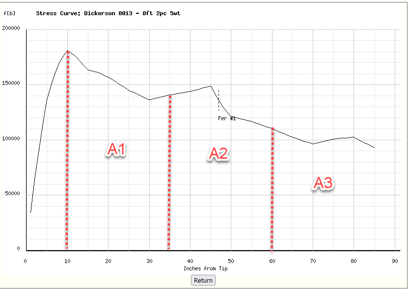
The area (sum of stresses) in the A1, A2 and A3 regions is caclulated.
The three measures are defined as follows:
- "Tip Action" captures the concentration of high stresses in the A1 region
as T=2A1/(A2+A3).
- "Middle Strength" captures the concentration of low stresses in the A2 region.
M=(A1+A3)/(2A2). Middle strength is sometimes associated with rods casting
more than one line weight well, or casting at a variety of distances effectivley.
YMMV of course.
- "Parabolic" captures high stresses in the A3 region. P=2A3/(A1+A2).
These three measures are scaled to sum to 1.0 in the table.
- A series of papers by Jon Hoffmann and Matthew Hooper explore the application
of engineering theory to fly rods, in particular the "natural frequency" of
tapered cantilever beams, and what it can tell us about the action of rods.
In the paper "Fly Rod Performance and Line Selection" (Proceedings of DETC'97/
1997 ASME Design Engineering Technical Conferences/ September 14-17, 1997,
Sacramento California), they analyze the frequency of 19 contemporary graphite
rods, and apply the theory to derive estimating equations for rod stiffness,
natural frequency, and line weight. This table gives some of engineering
quantities as estimated for the bamboo blank. They may prove useful in
comparing rods.
- The Estimated for Bamboo table takes the above measures from
Hoffmann and Hooper and adjusts them
for bamboo, based on the measured frequency for a small number (10) trout
sized rods of hexagonal construction. Please do not take these as more than
crude guesses. The line weight predictions were tested on 26 "classic" trout
tapers; the estimates are too high for more parabolic rods.
One of the uses of Hexrod is to modify an existing taper in a systematic way.
There are several options for doing this.
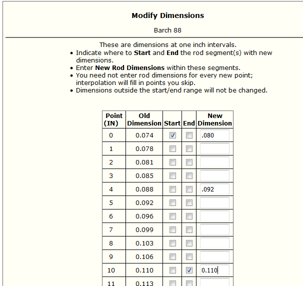
- Modify dimensions: If you want to replace the taper in a certain region
with different dimension numbers (e.g. to strengthen a tip or add a hinge),
you can directly
change the numbers in that region. The example below beefs up the tip from 0 to 10 inch
stations.
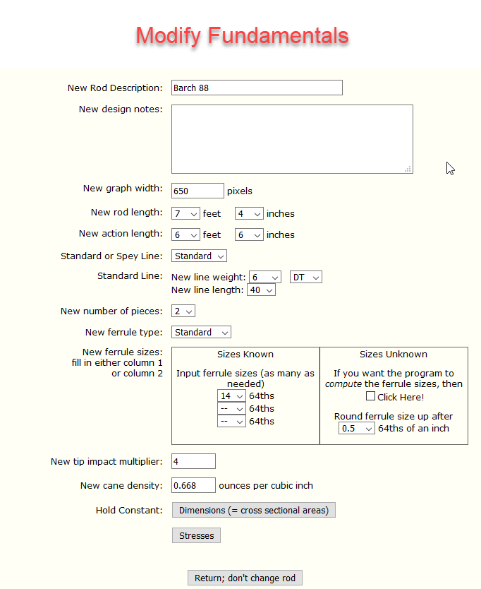
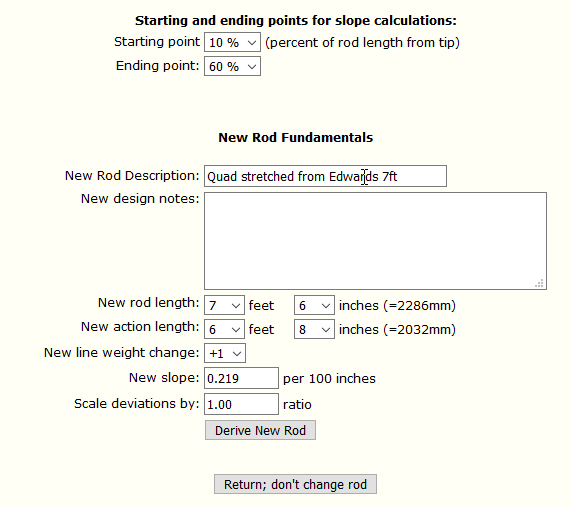
- Modify fundamentals. You can change the fundamentals of the rod, such as
length, line weight and number of pieces. The new rod taper is created by
either Holding Constant Dimensions, which means shortening or lengthening the
rod at the butt end, or (more commonly) Holding Constant Stresses, which
stretches or compresses the Garrison stress curve and works backward to the taper that
gives the curve.
Additional information on taper modification at the end of
this documentation.
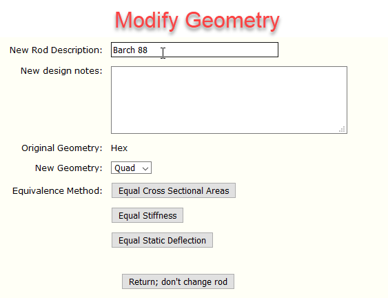
Modify Geometry gives two alternative conversions between Hex, Penta and Quad
construction dimensions. See Additional information below.
- Controlled modification. John Bokstrom's method of controlled
modification is a simple technique for replicating a taper in a rod that is
a little longer or shorter, lighter or heavier than the original. It
starts with a straight line taper drawns from the 10% and 60%
points along the rod length. Deviations of the actual from this straight
taper are calculated. The method of controlled modification then stretches
or squeezes these deviations to change the rod length, or shifts the straight
taper up or down to change line weight.
Additional information at the end of this documentation.
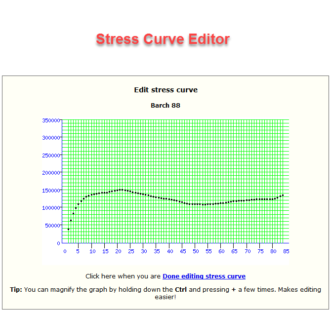
- Edit stress curve. The editor presents the stress curve graph as
a series of dots at one-inch intervals. Use your computer mouse to move the
points of the curve to increase or decrease stress in regions of the rod.
Then the dimensions will be computed for this new curve. It is not the most
elegant tool but serves the purpose.
- Output units: Change between American and metric output units.
- Hollowing:
Hollowing should be the last thing you attempt in Hexrod, after other modifications
and adjustments are complete.
Hexrod allows for hollowing by scallops and dams, where it assumed the
dams are as small as practical. In Hexrod, hollowing accomplishes two
things. First, you can adjust the dimensions to account for the hollowing
with either of three alternative methods, and you will add the hollowing
(wall thickness) to the planing form report for your reference. Stress
computation incorporates the hollowing.
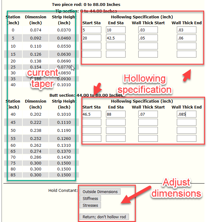
The hollowing procedure consists of two parts. First is specifying the
wall thickness. This is done separately for each section of the rod.
You can indicate where the hollowing begins and ends, and the wall
thickness for that segment at the beginning and end points.
This allows the wall thickness to have a linear taper.
Up to four separate beginning/ending segments
are allowed for each rod section. See the example below.
The second part is how dimensions are adjusted to compensate for the hollowing.
First option is leave the dimensions unchanged, which is most appropriate
when the degree of hollowing is modest. Second is to increase the taper to
maintain equal stiffness. This option uses the cubic formulas derived by
Mike McGuire and given in a paper "Dimension Compensation for Hollowing
Bamboo Rods" on his website. It is probably the most used method.
Unless the hollowing is extreme, the increase in outside dimenions will
probably be very small, at most a few thousanths of an inch.
The third is to adjust the taper
for equal stress, which may actually mean a decrease in dimension because
of the decreased weight. Weight reduction depends on the density of the cane,
which is initially set at 0.668 ounces per cubic inch (Garrison's calculation
for Tonkin cane). This can be changed on the Modify Fundamentals page.
Finally, the fourth way is by equal casting deflection. Like equal stresses,
dimensions in part of the rod may decrease while others are increased, because of
reduced bamboo weight. This is equal to maintaining deflected stress. Again,
actual external dimension changes will be small.
The following options (Report, Change, and Unhollow) are only available
for newly-hollowed rods (since 20-JAN-2010).
After hollowing, there is a report which gives the change in bamboo weight from
the original taper for each inch and section of the rod. This does not include
what you leave for dams, which might be 10-20 % of the weight reduction.
The hollowing specifications can be changed and the rod dimensions recalculated.
The hollowing can also be cancelled and returned to the original solid taper.
It is recommended NOT to change the length or geometry of a hollowed rod.
Do this operation first on a solid rod, then hollow.
Additional information at the end of this documentation.
- Modification by deflection curve.
See additional documentation below.
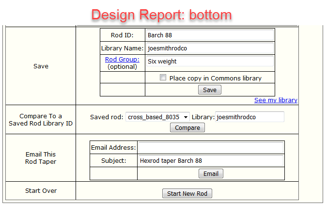
You can set up a private library to save your tapers.
Choose a name for the library you will
remember; the first time you save a rod your library will be created. You will
be asked for your name and email; this will help me solve problems
later (like people forgetting their library name). Library names are case sensitive.
You can set up more than one library if that suits your purpose.
Each taper in the library will have a distinct name (the Rod ID), and date. You can also assign
a group name
to the taper. In listings of tapers, rods will be listed by group.
To retrieve a rod from your library, enter the Rod ID and Library on the first
Rod Design Parameters page. If you enter a Library with no Rod ID, you will see
all rods in the Library and you can retrieve the one you want.
You can compare the current rod to one previously saved in a library. The comparison
gives graphs and tables for dimensions and stress values.
A list of your tapers can be sent to you (or someone else) by email.
- Tip sizes get tiny
- If you go back and forth, calculating stresses from dimensions then
recalculating dimensions from stresses, the dimension values in the first
few inches of the rod tip get tiny.
Garrison did not use the dimensions near the tip from
his math either; he considered these computed dimensions impractically small.
- Browser reload
- Because of the way information is passed between program screens,
a browser "Reload" will sometimes bring back a screen without data. Use
the "Back" button to go back to a good screen, reload it, and go forward
again. This can affect how you correct entry errors; you may have to
return and fill in the entire screen again.
- Units
- Hexrod allows specification of American (inches) or Metric (millimeters) for
three separate operations:
- Input of the rod (stations and dimensions)
- Output of tables and graphs
- Planing form settings
The length of
rod and the action length are input in American units (feet and inches) on
the first form page. After this point, you have the choice to input dimensions
and stations in inches or millimeters.
Planing form settings seem to be standardized on 5 inch (127mm) stations so these are
the default, and ferrule sizes are in 64'ths of inch, with metric sizes and weights
displayed.
All input rod measurements, American or metric, are interpolated to 1-inch
segments for stress calculations and then back again to metric for display.
Ferrule size are in 64ths of inch and stress values are computed and
displayed in American (ounce-inches), as are Morgan hand mill settings,
at least for the present.
Its harder to explain than to use.
- Rod and action length
- In case there is any confusion, the Rod Length refers to the
entire assembled rod, from tip to butt. The Action Length is the
length from the tip to as far as you want to analyze dimensions and
stresses.
The action length may end at the front of the grip, or may extend
into the grip and reel seat. It should never be longer than the rod length.
If you have a two-piece rod with unequal sections,
you can analyze
it by cheating a little. Specify the action length as usual, but
specify the rod length as twice the tip length, whatever that is.
That will place the ferrule where it should be for the stress calculations.
- Line weight & taper
-
Separate line weights are used for DT
and WF lines. These were compiled/computed from the Cortland website by
Chris Carlin. They specify the weight of each foot of line for each taper
and line weight from 2 through 12. One-weight lines are extrapolated from 2-weight
data using the AFTMA line weight standards.
Line weights 3/0, 2/0 and 0 were extrapolated
from the data for 1-weight lines by using the info on Bill Byrd's website
www.byrdultrafly.com/sagelines.htm. To my knowledge, there are no AFTMA standards for these line weights.
- Spey lines
- For spey-type lines, enter the weight of the entire head section
(including any added tip)
and the length of the running line cast. E.g. for a 35-foot head section
and a 80 foot total cast, the running line cast is 80-35=45 feet.
There are many sorts of running lines on the market.
It is assumed to weight 3.0 grains per foot, which seems typical.
- Tip impact factor
- Garrison incorporated this parameter (estimated to be 4.0) in his stress equations.
This number servs as a multiplier
for all the moments (line, bamboo, guide, varnish) to account
for the stress created by pulling the line through the air during the
cast. Increasing it will increase the stress values calculated.
Change it if you like, but make sure its the same when comparing stress numbers
of two rods.
- Tip factor
- is the weight of the line beyond the tip
(and the weight of the tip guide, fwiw).
- Cane density
- Garrison calculated the denisty of Tonkin cane as 0.668 ounces
per cubic inch. This parameter may be adjusted if you are
building with another material.
From the point of view of stress calculations, the only thing
about a ferrule that matters is its weight (and its location, of course).
Ferrule weights are supplied for sizes 8 thru 32 -64th in standard
and truncated lengths. They correspond most closely to nickel silver Super Swiss
style ferrules of the type produced by CSE. Some of the weights
come from Wayne's original program, from measurements others have
sent me, and from my own limited measurements. Some in-between sizes
I've estimated as best I could. (Yes, someone requested ferrules as
large as 32/64!)
If you are using a ferrule that is unusual in material, type or size.
and you know its weight in ounces, use the table below to choose
the size and type (standard or truncated) that most closely matches the
weight, and then use that ferrule "as if" it were the correct one.
Tell the program not to adjust the ferrule size.
| Wt (Oz/g) |
Size |
Type |
Wt (Oz/g) |
Size |
Type |
| 0.075/2.126 |
8 |
Truncated |
0.437/12.389 |
17 |
Standard |
| 0.084/2.381 |
9 |
Truncated |
0.442/12.530 |
24 |
Truncated |
| 0.095/2.693 |
10 |
Truncated |
0.466/13.211 |
25 |
Truncated |
| 0.117/3.317 |
11 |
Truncated |
0.477/13.523 |
18 |
Standard |
| 0.120/3.402 |
8 |
Standard |
0.490/13.891 |
26 |
Truncated |
| 0.135/3.827 |
9 |
Standard |
0.514/14.572 |
27 |
Truncated |
| 0.141/3.997 |
12 |
Truncated |
0.516/14.628 |
19 |
Standard |
| 0.162/4.593 |
10 |
Standard |
0.537/15.224 |
28 |
Truncated |
| 0.163/4.621 |
13 |
Truncated |
0.556/15.762 |
20 |
Standard |
| 0.194/5.500 |
11 |
Standard |
0.560/15.876 |
29 |
Truncated |
| 0.197/5.585 |
14 |
Truncated |
0.584/16.556 |
30 |
Truncated |
| 0.225/6.379 |
12 |
Standard |
0.595/16.868 |
21 |
Standard |
| 0.238/6.747 |
15 |
Truncated |
0.607/17.208 |
31 |
Truncated |
| 0.247/7.002 |
16 |
Truncated |
0.630/17.860 |
32 |
Truncated |
| 0.271/7.683 |
13 |
Standard |
0.633/17.945 |
22 |
Standard |
| 0.272/7.711 |
17 |
Truncated |
0.672/19.051 |
23 |
Standard |
| 0.297/8.420 |
18 |
Truncated |
0.711/20.156 |
24 |
Standard |
| 0.321/9.100 |
19 |
Truncated |
0.749/21.234 |
25 |
Standard |
| 0.328/9.299 |
14 |
Standard |
0.787/22.311 |
26 |
Standard |
| 0.346/9.809 |
20 |
Truncated |
0.825/23.388 |
27 |
Standard |
| 0.358/10.149 |
15 |
Standard |
0.863/24.466 |
28 |
Standard |
| 0.370/10.489 |
21 |
Truncated |
0.900/25.515 |
29 |
Standard |
E.C. Powell tapers are created from a formula, starting with
"A", "B" or "C" families.
Powell "B" tapers start with a tip size and a linear taper,
given in thousanths of an inch per six inches of rod strip. E.g. a B-8 taper
has the strip increasing 0.008 per six inches (the total rod dimension
increasing 0.016 per six inches.) A B-9.2 taper increases 0.0092 per six inches.
"A" and "C" tapers modify the linear "B" taper formula by adding (A) or subtracting
(C) a fixed amount to the strip each 6 inches after the frist 6-inch station.
This amount is given as a fraction of a thousanth of an inch; 1/5 is 0.0002
inches.
An A-8 X 1/5 taper has the strip increasing 0.008 from the tip to six inches,
0.008+0.0002=0.0082 from six to 12 inches, 0.0084 from 12 to 18, 0.0086
from 18 to 24 inches, etc. Powell characterized the A-series rods as "progressive."
"C" tapers substract the fraction at each 6-inch station after the first. These
are "regressive" tapers.
Powell tapers are most commonly used for longer (8 foot plus)
rods in heavier (5+) line
weights, and are usually hiollow-built.
There is no fixed formula for choosing the initial tip size or
line weight of a rod. If you create a taper and take it into Hexrod, you can adjust
the line weight after viewing the stress values.
Input for Powell taper calculator is in American units. If you specified Metric
output, this will appear on subsequent screens.
The Hexrod implementation of Powell tapers is based on the article by Ed Hartzell
in The Planing Form, number 54 (1998).
This approach to modifying a rod's fundamentals seems to be the safest:
- First, make changes to the original rod's simple properties
such as changing length, number of
pieces, ferrule type, line weight or length of cast.
- Second, if desired, change the rod's geometry.
- Finally, again if desired, hollow the taper to your specifications.
Changing Simple Properties
Changing one or more "fundamentals" of a rod without
changing the taper will change the stress values, or conversely, fundamentals can be
changed while preserving the stress values which will change the taper. In Hexrod this
is accomplished by choosing the �Modify Fundamentals� option, changing
one or more fundamentals,
then choosing either "Hold Constant Dimensions" (for new stresses) or "Hold Constant
Stresses" (for a new taper.)
When calculating a new taper for a changed rod by holding constant stresses, be aware
that the sizes of the ferrules may change. In Hexrod, be sure to click the checkbox under
Ferrule sizes Unknown.
Many builders have found that, making modest changes to a rod while holding
constant the stress values will result in a rod with a similar "feel."
For example, changing a 7.5 foot 4 weight rod to a 8 foot 5 weight is
reasonable. Going from that rod to a 9 foot 7 weight is not likely
to succeed.
- Number of pieces
- A common modification is to change the number of pieces in a rod by
adding or removing ferrules from the taper. Adding a ferrule (say from a 2 to 3
piece) adds considerable weight at certain points, which increases moments and
increases stress. Adding a ferrule will add stress from that location back toward
the butt. If we want a new rod with the same stress characteristics, we will have to
increase the taper dimensions from that point backward to support the additional
weight without increasing the stress.
Changing the number of ferrules will involve computing not only the locations but
the sizes of the ferrules.
Naturally, adding ferrules does more than add weight. It also introduces a flat
spot to the taper. Not all tapers will respond well to changing ferrule locations.
In general, ferrules are least objectionable in a fairly low stress part of the taper.
Many classic tapers used step down ferrules; the taper was designed for a ferrule
at that particular location and moving it will alter the feel of the rod.
Besides the number of ferrules, it is possible to change ferrule types, from standard
to truncated or the opposite. This will change the weight, which will change the
stress, or change the taper to achieve the same stresses.
- Line weight
- Changing the weight of the line, or the type of the line (weight forward,
double taper, or spey), or the length of the line cast will alter the stresses.
Conversely you can hold constant stresses and derive a new taper that will give
the same stresses with the new weight. Logically, adding line weight will increase
moments which will increase stresses; to achieve the same stresses the taper will
have to be beefed up.
- Rod length
- Following Garrison, stress values are calculated starting at the tip
and ending at the top of the grip. This is called the "action length". For a typical
trout rod, it is about 10 inches shorter than the entire rod.
Action and rod lengths can be changed in Hexrod. If dimensions are held constant,
a shorter rod just means ending the taper earlier, and a longer rod extends the
taper near the grip a little longer. If stresses are held constant, then the stress curve
is compressed to shorten the rod or stretched to lengthen it. The new taper is
computed from this altered stress curve.
Changing the Geometry
There are two methods available to change the geometry:
- Find a new taper with equal cross section at each station to the original. This
is the "traditional" method. It results in a rod with equal weight to the original. The constants involved and their derivation can be seen
here in section 7.
- New taper has equal stiffness (Moment of Inertia) to the original. This is the
preferred method of many builders. The constants are in section 9 of the above
reference. A series of spread sheets are available to do the
conversion has been created by Gabriele Gori and is available
here
The option to modify geometry by equivalent Garrison (static) stress curve
has been removed as of April 2021. It tended to give impractical tapers.
The option to change geometry by equivalent casting deflection curves
has been removed until a problem with convergence is resolved.
There are many hollowing schemes in use. Hexrod assumes scalloping with dams
in its calculations.
The effect of hollowing on stress is hard to predict in advance. Hollowing
reduces weight of the rod (the "bamboo moment"); this reduces stress compared to
a solid rod, the difference increasing as you move toward the grip and becomes magnified
in longer (e.g. spey) rods. Countering this, hollowing
also decreases the stiffness (Modulus of Elasticity)
of the rod at each point; this increases stress values.
Which one of
these effects dominates depends on the degree of hollowing and length of the rod.
It is possible that stresses decrease in some areas of a rod while increasing in others.
Placement of ferrules can also affect how these two components
balance out.
Most often, the effect of modest hollowing on
stress values is quite small for a trout-sized rod, but can be significant for a longer rod.
The formulas for stress in a hollow rod can be found in the toward the end of the
paper by Claude Freaner
on this website.
Computing dimensions while holding constant stresses (e.g. a hollow rod with the
same stress
curve as a solid rod) is an iterative process, working down the rod from tip to butt.
Iteration at an inch-point stops when stresses
are within 10 ounce/inches of
the target stress, or change in dimension is less than 0.0001 inches. Then
the process advances to the next inch. This will typically take a couple seconds.
Be aware that bamboo is not of uniform strength. Milward's book "Bamboo: Fact Fiction and Fly Rods" documents how rapidly the stiffness (Modulus of Elasticity) decreases
as you go from enamel to pith. Hollow building is removing much weaker material than
what remains. This fact does not enter into the stress calculations. Therefore,
building a hollow rod with equal stress to a solid rod will probably result in a stiffer
rod than you anticipate.
Static deflection calculates the bend of the rod assuming a force (weight)
suspended from the tip of the rod. It uses mechanical engineering concepts
for deflection of a cantilever beam, as implemented by Bennett Scully in
his
Honors thesis.
Deflection calculations rely on a fairly complex set of assumptions, some of which are
- Small deflection theory is implemented by treating the rod as a set of small
increments, and then accumulating the deflection. Hexrod uses increments of length
0.2 inches. Large deflection theory is significantly more complex.
- Static deflection ignores other forces which cause a bamboo rod to
deflect. It ignores the weight of the rod components (bamboo, ferrules, varnish
and guides), the weight of the line being cast and the line in the guides. It also
ignores the forces involved in casting. These are treated in dynamic or casting
deflection analyses.
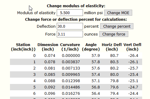
- Modulus of elasticity (MOE or E) is a measure of the inherent stiffness of the
bamboo. Several researchers have measured the MOE of Tonkin cane, most often used
in rodbuilding. But there is considerable variability between culms and even between
strips in the same culm. Due to the decline in power fibers from enamel to pith,
there is also an expected decline in MOE from tips (built from just the outer
portion of the strip) to butt. I worked with the MOE results published by Bob Milward
in Bamboo: Fact Fiction and Flyrods, and arrived at a default MOE of 5.3 million psi
(= 36.54 gigapascals); this value can be changed by the user. Max Satoh's DynaRod
program contains MOE values for various species of Japanese bamboo.
Usage
The output from static deflection includes a graph and a table. The graph starts
by default with the force necessary to deflect the rod 30 percent of its length.
E.g. for an 8 foot rod (96 inches), this is a deflection of 96 x 0.3 = 28.8 inches.
The user can then change the deflection percent or the force. The MOE can also
be changed from the default. The table contains deflection values by inch.
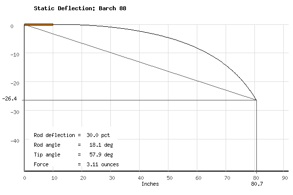
The option to compare the active rod with another in your library will
give a graph comparing the static deflection curves for the rods on the
assumption of 30 percent deflection.

Casting deflection (as contrasted with
static deflection) includes the weight
of the rod and components involved in the cast: weight of bamboo, ferrules,
varnish and guides, the line in the guides, and the line being cast. These
are the same components, along with the "impact multipler" (G force), that
are involved in computing the traditional Garrison stress
curve, which tradionally uses the impact factor at 4G.
In addition, the casting deflection involves the resistance to bending
(MOE) of the bamboo.
(I chose the name "casting deflection" rather than the more obvious "dynamic
deflection" because it leaves out many elements that would be included in
a realistic "dynamic" analysis: the variable input of force from the caster at different
points during the cast, the changing angle of the line to the rod, etc.)
Calculation of casting deflection employs the same algorithm by Scully used in
static deflection, with several modifications. It requires many iterations and
will sometimes take 5-10 seconds to display the initial page.
The casting stress values are calculated from the curvature of the deflected rod,
the MOE and rod dimensions. It is interesting (to me :-) to compare these
stress curves for various impact factors to the Garrison curves for the
undeflected rod. The total area under the stress curve may have no
intrinsic meaning
but provides a metric for comparing curves under different assumptions.
The graph of the casting deflection curve includes a casting torque measure,
which is the rod moments calculated using the deflected length, summed
at the end the the action length, usually the start of the grip. It
may be useful for comparing the perceived rod weight of different rods which
are casting the same weight and length of line.
This procedure has been temporarily (April 2021) removed
until I have time to investigate some convergence issues.
John Bokstrom developed a graphical system for creating a new rod by modifying
an existing taper which he called Controlled Modification. It was written up in
The Planing Form issue 45. It is intended to allow modest changes in rod
length and line size while maintaining the same feel.
This is how it works.
Dimensions of the existing rod at two points, 10% and 60% of the rod length from
the tip, are used to define a straight line with an intercept and a
slope (expressed
in inches of rod dimension per 100 inches of rod length). Then at each inch-point
the deviation of the actual rod from this straight line taper is calculated.
The essence of Bokstrom's method is to replicate these same deviations from
the straight line in a new rod of a different length.
To create a new taper for a longer or shorter rod, the straight line taper
is extended or shortened, and then the curve of the original deviations
is stretched or compressed
and applied to the straight taper. If a different line weight is desired,
the intercept of the straight taper is adjusted by appoximately 0.007 inch
per unit of additional line weight.
If desired, you can change the 10% and 60% start/end points for determining the
straight line taper. Also, you can magnify or reduce the deviations around the
straight line for the new row by a multiplier. Intuitively, you may want a multiplier
less than 1.0 if shortenting the new rod, or greater than 1.0 if lengthening.
The Bokstrom modification is just applied to the action-length portion of the rod.
The dimension beyond the action length (e.g. under the rod handle) is given no taper.
If the rod changes length, ferrule locations and sizes are allowed to change.
Finally
If you find any bugs, have suggestions for improvements, etc. let me
know at
fcstetzer at gmail dot com.
Just for the record, I promise not to peek at anyone's rod designs :)
Back to the Hexrod Program
--
Frank Stetzer
Bellingham Washington, USA